What
There are many ways to make your own electronic circuits. The 3D milling and scanning machine (part of the FabLab) offers one of the quickest and most precise tools to do so.
What do you need to know (aside from basic knowledge of electronics) to make your own electronic circuits with th 3D milling? Marc Boon will guide you through the steps, from designing a (simple) electronic circuit, preparing the design for the 3D milling and scanning machine and the milling of the circuit. As case the participants will make a micro television.
Workshop report
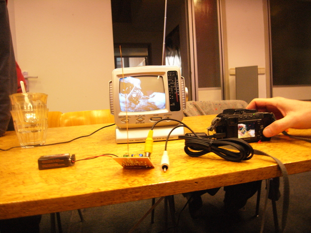
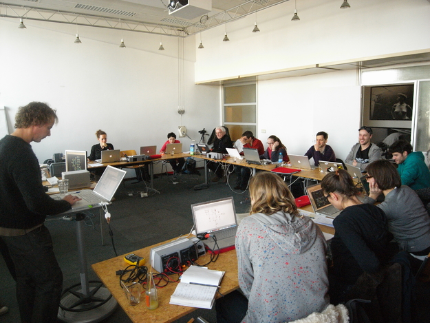
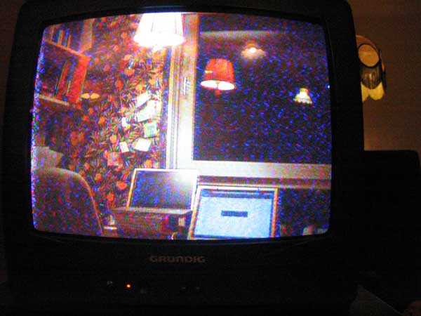
Again a wonderful sunny morning with a clear blue sky and a beautiful view on Amsterdam from the Mediamatic workshop space. But this time there is something in the air - or at least there will be something in the air later that day when each participant of the DIY Electronic Circuits Workshop will have built their own MicroTV transmitter!
So let's get started: After a short introduction of the workshop guided by Marc Boon, a mediator between art and technology, and Bernardo Gaeiras from the Mediamatic FabLab, everybody had a clearer picture about the exciting new techniques this workshop was dedicated to.
Usually the production of electronic circuits (PCB's) takes a couple of different steps until you have turned a plain copper plate into a filigree network of conductive paths by means of photochemical processes. But especially for a small edition of self-designed circuit layouts this common procedure is often a bit too tedious for quick prototyping or last minute birthday-presents. So why not making use of the enormous precise fab tools that are more and more available in small prototyping facilities for quick and easy "getting things out of the computer into the real world"?
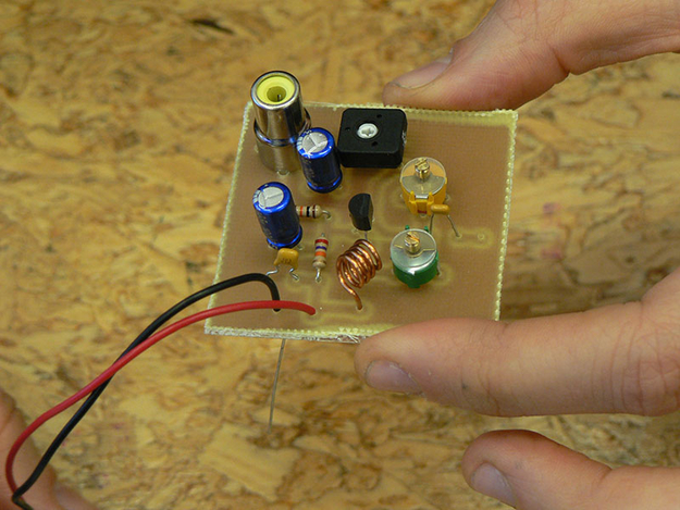
As an example circuit Marc brought the schematic of a micro television transmitter (designed by Tetsuo Kogawa) which can transmit video signals that can be received by a common analog television with an antenna. The first thing to learn was how to design a circuit layout in the free available Eagle software: First decide which parts are needed, place and connect them to a schematic which than can be converted into the proper board layout. If it would be that easy...
But everybody mastered that challenge and so the schedule went on to the real FabLab magic:
Marc wrote a script so that it is possible to create milling instructions from the circuit layout directly from Eagle which can be sent to a 3D-milling machine in order to let this mill the circuit paths and drill the holes for mounting the parts in one step! After adjusting the copper plates in the milling machine and changing some coordinates the production process started and was enthusiastic observed by everybody around.
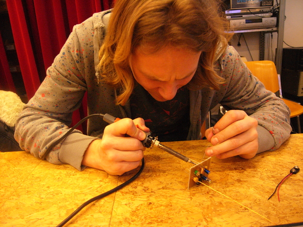
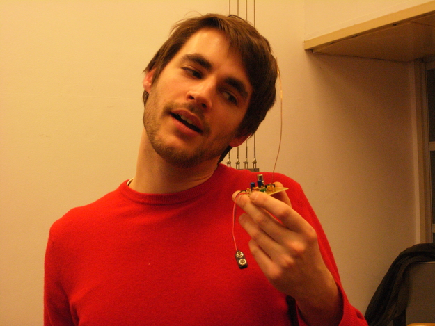
And after a while every participant had his own fabricated little board on which now only the electronic components had to be soldered on. And I can confirm that it is really fun to solder things on your own fabbed circuit!
For a detailed walk-through on how to make printed circuit boards with the Fab Lab see: fablab.marcboon.com/pcb/
